 Aerated Concrete Block Industry
  Brewery Industry
  Captive Cogen Industry
  Chemical Industry
  Dairy Industry
  Edible Oil Industry
  Fertilizer Industry
  Hotel Industry
  Pharma Industry
 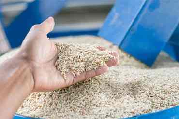 Rice Industry
 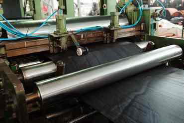 Rubber Industry
  Soap Industry
 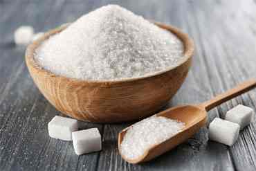 Sugar Industry
  Textile Industry
  Tyre Industry
 Condensate pumping from vented receivers
UKL pumping terminology includes Static Head and vapour pressure including detail of operation, application.
UKL has also described benefits of mechanical condensate pumps against electrical centrifugal maintenance cost occurring.
Parameters considered
Vapour pressure-It used to define the pressure corresponding to the temperature at which a liquid changes into vapour i.e. pressure at which a liquid will boil.
- At 100°C, water will boil at atmospheric pressure.
- At 170°C, water will boil at a pressure of 7 bar gauge.
- At 90°C, water will boil at a pressure of 0.7 bar absolute.
When pumping condensate the vapour pressure is plays a vital role. Formation of condensate at a temperature close to its boiling point causes difficulties for centrifugal pumps for pumping due to area of lower pressure at center of the impeller with condensate already very close to its vapour pressure which generates steam bubbles. During its travel, these bubbles causes cavitation due to bursting of steam bubbles. Such parameters are addressed by UKL condensate pump suitable for condensate temperatures in atmospheric systems with Temp not exceeding 98°C.
Head - Head is a term used to describe the potential energy of a fluid at a given point. Which is measured as pressure head, static head and friction head.Static head for water of 10 meters is approximately equivalent to a pressure head of 1 bar Gauge.
Pressure head - Pressure head is the fluid pressure at the point in question. For more clarity consider a pump required to discharge water against a static head of 40 meters, which approximately equals a pressure head of 4 bar g. The pump fills from a static head of 2meter, which equals a pressure head of 0.2 bar g.
Static head –Is equivalent to vertical height of fluid above a datum. To explain further, the pump when subjected to a static /suction/fillinghead of 1 m, and discharges against a static/delivery head of 30 m. This case, the water is being pumped above the pump inlet termed as flooded suction.
Net static head - depends upon Type of Pump as centrifugal type pump or a positive displacement mechanical type pump.
In centrifugal Pump, net static head, against which the pump has to work, is the difference between the suction head and the delivery head. Pressure exerted by the suction head is always present in the pump.
In Condensate displacement pump the suction head only provides the energy to fill the pump during the filling cycle. The net static head is equals to the delivery head. It is not present in the pump body during pumping and has no effect on the delivery head against which the pump has to operate.
Friction head - The friction head defined as the energy required to move the fluid through the pipe.
Pressure loss can be calculated with Steam distribution network or is usually found from tables that correlate liquid flow rate, pipe diameter and velocity. The resistance to flow encountered by various pipeline fittings to be considered.
The extra length for pipe fittings is then added to the actual pipe length with additional 10% of the actual pipe length which can be tabulated as
Total equivalent length = Actual length + 10%
For designing a system with manufactured pump arrangement, the figure of 10% will be used as the equivalent length for calculating pressure loss due to friction which depends on velocity of water. Hence pressure loss due to friction increases by a factor proportional to the square of velocity.
Example for calculation :
The 50 mm discharge pipework on a pumped condensate line rises vertically for 29 mtrs to a vented tank. The line is 200 m long and the pumping rate is 5000 kg/h of water. What is: (I) the pressure head loss due to friction (the friction head), and (II) the total delivery head.
1 – To calculate pressure head loss due to friction (the friction head)
Total equivalent length (le) = 200 + 10% = 220 meters
From Steam table it is observed that 50 mm pipe carrying 5004 kg/hr of water will experience a pressure drop of 1.0 mbar /m. Pressure head loss calculated as :
220 meters x1 mbar/m = 220 mbar (0.220 bar). Considering 1 bar to be equivalent to 10 meters of water head the equivalent friction head loss in terms of meters is:
0.220 bar x 10 m/bar = 2.20 meters.
II - The total delivery head
Total delivery head (hd) - The total delivery which the pump needs to operate is the sum of three components.
The working of electrically operated centrifugal condensate pumps
Pump operation
Condensate is directed into the Centre, of the rotating impeller vanes which gains velocity while traveling towards the outside of the impeller.
Pump application
These are applied large volumes of liquid need to be transported. Nomenclature for electrical pumps are condensate recovery unit (CRU) which includes receiver, control system and 1 & 2 pumps.
The pumping rate is considered as opposed to the rate of condensate returned the receiver for calculating the frictional loss in the discharge line for a CRU
For heavy load, twin pump units, a cascade control system can also be employed with one as stand-by providing back-up in the case of the one pump failing to operate; the condensate level in the tank will increase and bring the stand-by pump into operation.
Selecting an electrical condensate recovery unit
- The condensate Load.
- The temperature of the condensate
- The total discharge head will be determined from the site conditions.
- The pump discharge rate has to be designed considering the manufacturer’s in order to size the return pipework.
Considering an typical example for Sizing discharge pipework for an electric condensate recovering Unit
Temperature of condensate = 94°C
Condensate to be handled = 2700 kg/hr
Static lift (hs) = 6 m
Length of pipework = 200 m
Condensate backpressure = friction losses only (hf)
From the UKL chart, CLP 50 actually rated to handle 3000 kg/h of condensate against a maximum delivery head of 10 m.
The condensate return line is sized on the maximum pumping rate at the required delivery head.
Maximum pumping rate = 3000 kg/h
Actual length of pipework = 200 m
Equivalent length of pipework = 200 m + 10% = 220 m
Estimating the friction loss in the pipe (hf)
To size a pumped discharge line it is usually a good idea to begin the friction loss calculation with an arbitrary pressure drop of between 100 and 200 Pa/m
From the table for 4 Kg/cm2 motive pressure line picking up 10 Meters delivery Head, Pump size 50 will be suited.
It can be interpolated from Pressure Loss calculation, that a flow rate of 2700 kg/h will correspond to a pressure drop of 128 Pa/m, for 50 mm pipework,
The head loss to friction can now be calculated for 50 mm pipework.
Head loss to friction (hf) = 110 Pa/m x 220 m
hf = 21120 Pa
hf = Approximately 2.1 meters
The total delivery head against which the pump has to discharge is therefore hs + hf = hd, where:
hs = static lift of 6 m
hf = 2.1 meters
hd = 06 m + 2.1 m = 8.1 meters
Hence required delivery head of 8.1 meters to be pumped for condensate load of 2700Kg/hr with motive steam pressure of 4Kg/cm2
Optional way for selection of delivery pipework
With an actual static head (hs) of 06 m, and design head of 30 m, 24 m head is available for pipe friction losses (hf) making it possible to install a smaller diameter pipe and have a larger friction loss. Velocity also needs to be checked against a typical maximum of about 3 meter/second allowable for pumped water at temperatures below 100°C.
If we consider next lower sized pipe (40 mm) were chosen, the unit friction loss (hf) to pass 2700 kg/h is interpolated to be 220 Pa/m, and the velocity is about 1 m/ s, which is below 3 meter/second and therefore suitable for the application.
hf is 220 Pa/m x 220 m = 48400 Pa (or 4.84 m)
Therefore, total delivery head (hd) = hs + hf
hd = 6 + 4.84 m
hd = 10.84 m
The conclusion is that a 40 mm pipe could be used, as the CLP 50 pump can handle up to 10.84 m total delivery head which is reasonably close to design and hence CLP 40 cannot be suggested.
UKL Positive displacement Mechanical condensate pump?
The pump operation
The body contains a float mechanism, which operates a set of changeover valves. A mechanical pump consists of a body shell, into which condensate flows by gravity. Condensate when flows into the body in turns raises the float. When the float reaches a certain level, triggering a vent valve to close, and an inlet valve to open, to allow steam to enter and pressurise the body to push out the condensate. The condensate level and the float both fall to a preset position, at which the steam inlet valve shuts and the vent valve re-opens, allowing the pump boy to refill with condensate. This works on Snap toggle mechanism. Inlet and Outlet Non-Slam Check valves are installed. A receiver is required to store condensate while the pump is discharging for cyclic operations.
Application of UKL Condensate Pump
- Cavitation is generated in Electrical pumps making UKL CLP condensate pumps more suitable
- Condensate is in vacuum.
- Constraint for space at plant.
- Very low maintenance cost.
- Hazardous, humid or wet environment.
- Non-availability of electrical supplies.
- Stalling conditions where condensate has to be removed from individual items of temperature controlled equipment
- No additional control system is required as the pump is fully automatic, No separate reservoir is required and operates when needed. This means that the pump is self-regulating.
The pump cycles as the receiver fills and empties. The flow rate while the pump is discharging can be consider to six times the filling rate which can be used to calculate the size of the discharge pipe also.
For selection mechanical condensate pump
- The maximum condensate flow rate reaching the receiver.
- Depending upon the application and site availability, the motive pressure of steam or air can be utilized to drive the pump.
- The filling head available between the receiver and pump.
- The total delivery head of the condensate system.
The method of sizing mechanical pumps Different manufacturer follow different method of selection.
Consider following example,
How to size a mechanical condensate pump
The discharge pipe can be same size as that of the outlet of Pump when it less than 100 m long since resistance of the pipe is small compared to the backpressure caused by the lift and condensate return pressure. For discharge pipes longer than 100 m, one pipe size larger than the pump outlet check valve, should be selected.
Discharge pipes longer than 100 meters
It is advisable to check the pipe size to ensure that the total friction loss does not exceed the pump’s capability when delivery lines over 100 m, and/ or where the condensate flow is near the pump.
Pump delivery lines longer than 100 meters for effect of Inertia.
When length increases over 100 m, a large volume of liquid will be held within the pump discharge pipe causing sudden acceleration of this mass of liquid at the start of the pump discharge can absorb some part of the pump energy and result in a large amount of water hammer and noise. This needs to be considered within the calculation by reducing the allowable friction loss.
The average time for the pump to discharge being approximately 25% of the total filling and discharge cycle time.
Fully loaded pumps and longer lines
Considering maximum pump filling rate with a motive pressure of 5 bar g and a delivery head of 20 meters is 2600 kg/h. Had the filling rate been close to this maximum, then less delivery head would have been available for friction loss. For the same size CLP 50 pump, this would mean a larger delivery pipeline
Taking same DN50 pump, having a condensate filling rate of 2000 kg / hr. Now determine the size of the delivery pipeline.
Sizing on a filling rate of 2000 kg/hr, and a steam pressure of 4 bar, referring to UKL Table, for the DN50 pump, it can be seen that a condensate filling rate of 2000 kg/hr equates to a maximum backpressure of about 25 meter.The discharge pipework sized on the flow rate from the pump outlet, which is taken as 4 x maximum pumping rate. 4 x 2000 kg/h = 8000 kg/h with a friction loss of 18 Pa/m pointing size of 80MM Size which is economical to consider a larger pump in conjunction with a smaller pipeline.
Suitable larger pump with smaller pipeline
Consider the same pumping conditions as but with DN80 pump, improved delivery head is achieved with smaller delivery lines.